The optimal negative feedback resistor
The feedback resistor from the output of a power amplifier to its inverting input is a component that in my opinion receives far too little attention. It should be clear that any property of this resistor that causes it to deviate from the ideal linear resistance directly results in a distortion of our signal. In this case no ring amplification with which one can compensate for many small errors inside the amplifier (except for the differential amplifier) will help.
An example: each resistor has a temperature coefficient Tc. Typically these are 50-100ppm/°C. If the amplifier is driven with a low frequency signal (e.g. 60Hz), then the feedback resistor, where the (almost) full output voltage is applied, is also modulated in temperature with this frequency. With thermal time constants of a normal 0207 resistor in the range of a few seconds, these are of course only a few milli degrees, but still. This changes the value of the resistor and thus the amplification of our power amplifier with our low frequency signal.
A tone of higher frequency (e.g. 7000Hz) is modulated in its amplitude, which results in additional, previously non-existent signal components. This results in additional signals with frequencies, in our example, of 7000Hz+-n x 120Hz. The 120Hz (and not 60Hz) are due to the fact that both half-waves of the low-frequency signal naturally heat up the feedback resistor, i.e. are quasi modulated with the rectified signal.
The whole thing is then intermodulation distortion (in the SMPTE variant). In terms of sound, this results in a less direct, precise and powerful bass than would actually be possible.
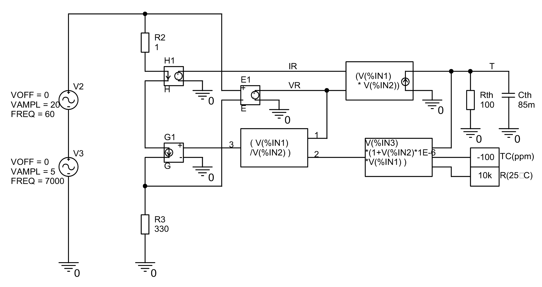
But what does it actually produce? Here is a simulation of such a feedback network:

Looks a little complicated, but it's not that bad. With H1, the current in the through our resistor simulation is measured. E1 measures the voltage drop. Both is multiplied in the following block and results in the resulting power loss (here as current) in our resistor. If you send this power dissipation (current) into the network of Rth (the thermal resistance of the resistor) and Cth (the thermal capacity of the resistor) you get the actual time dependent temperature of the resistor. This is then converted with TC and R25°C into the current resistance value. The applied voltage (VR) is divided by this value and output via the controlled current source G1. The model of a resistor is finished, taking into account its dynamic self-heating. R2 only serves the convergence of the simulation and has no other effect.
R25°C and R3 are the values for the negative feedback network which I typically use in my amplifiers.
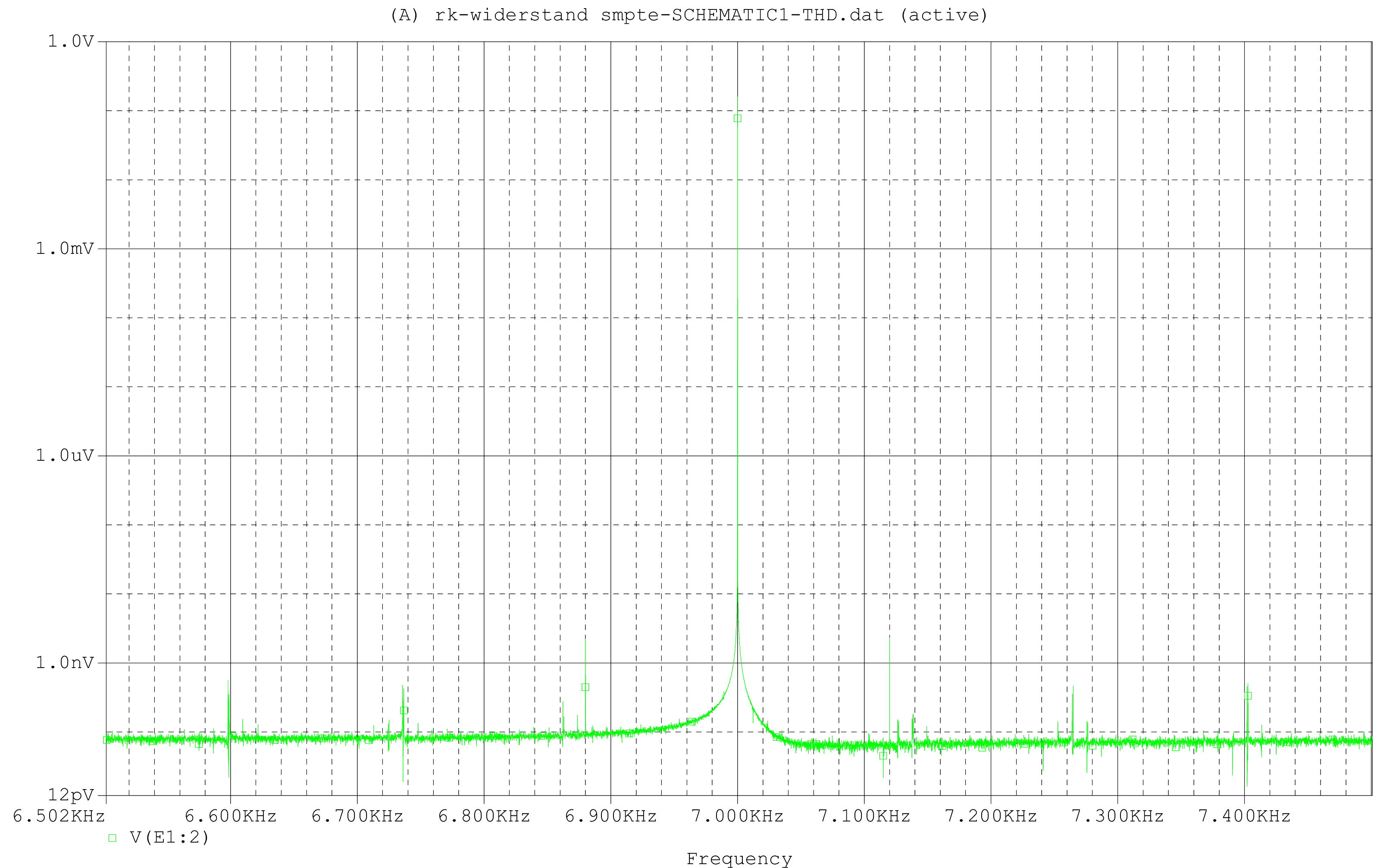
And here the simulation result:

Well, an IM distortion in the range of -160dB is complaining at the highest level, but you wouldn't be a high end if you didn't want to make it even better.
But be careful: with amplifiers with much more power, higher gain and above all lower resistance values in the negative feedback network it can quickly lead to disastrous results.
So what can you do: e.g. use a resistor with a much lower TC. You can buy it (but it can quickly cost more than €10,-) or search in the resistors from the tinkering box. Each resistor value of a series (e.g. 0207 from Beyschlag) has a different TC. My 10k resistors from the tinkering box have about 20ppm/°C, my 47k resistors of the same series have less than 2ppm/°C (I cannot measure better). For this I measure the resistors at room temperature and at approx. 90°C (hot air dryer).
Alternatively you can also connect several resistors in parallel and/or in series. This reduces the self-heating by distributing the power dissipation over several components and increases the thermal inertia. With 4 resistors this brings a factor of 16, i.e. 24dB.
I usually do both: in my case 4x47k and 1x68k in parallel and will have one of the best 10k resistors available in the world.
The search for the optimal resistor should be repeated with each new delivery. The TC unfortunately depends on the manufacturer, the series and the batch.


