")
")
Low Distortion Sinus Generator (1)
The first step towards a useful measurement system for the analysis of non-linearities of audio components is a highly linear sine wave generator. From my point of view it is sufficient if it can generate a few discrete frequencies. With 2 generators this is sufficient for SMPTE and CCIF measurements.
During my internet research I quickly came across an article by Robert Cordell from 1981. Here he describes a sine wave generator and a rejection filter circuit, which I consider very promising for my first attempt. I have implemented the whole thing with modern components available today. And lo and behold, at 1kHz and 0.7Veff output voltage the distortion (THD) is < -120dBV, so <0.0001%. The measurable distortion is completely in the 3rd harmonic (which probably points to the amplitude control with the JFET).
This is my current measurement limit and a (large) part of the distortion will probably also occur in the test receiver. With continuous improvement of all components, there is still a lot to be achieved.

Fig. Schematic
The circuit itself works with a state variable filter (OP1,OP2). The rest is the amplitude control with the rectifier (Q1,Q3) and the filters (U4), which keep the control loop stable. Critical is the voltage controlled resistor, which is realized with a JFET (Q4).
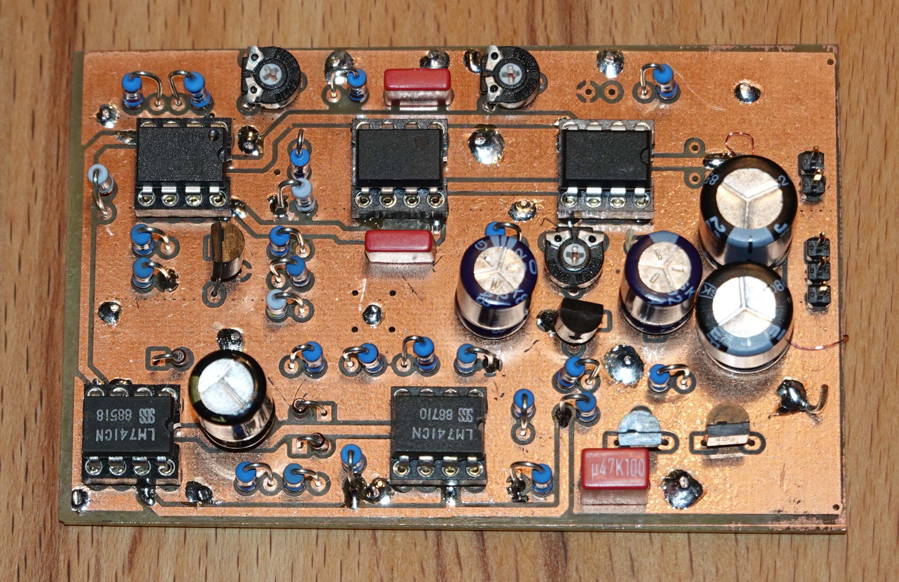
Fig. A first test setup with a self-made, double-sided printed circuit board. In a newer version I replaced the two uA741 by a TL072 (as shown in the schematic).
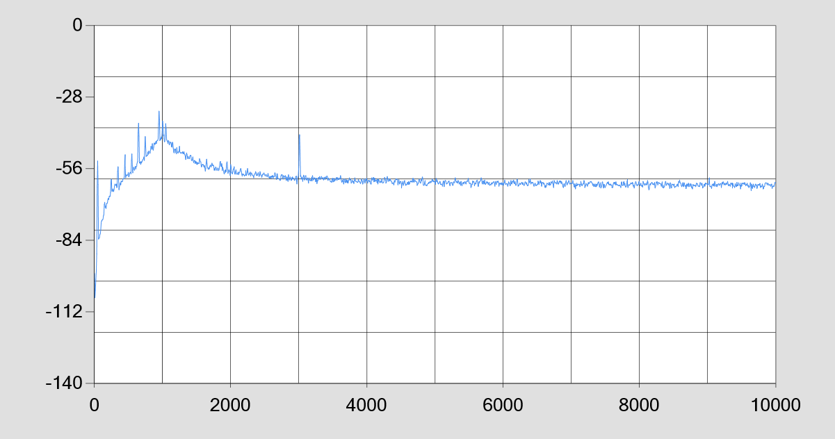
Fig. FFT of the distortion products. At 1kHz is the suppressed fundamental wave. K3 is at -43dBV, where the test receiver has 80dB gain. So K3 is at real -123dBV!
Low Distortion Sinus Generator (2)
The 2nd generation has received a few improvements.
1. 3(4) frequencies are switchable via relays. 2.
2. a reference signal of -80dB can be superimposed on the output signal (switchable).
3. the supply voltage can be switched via relays.
4. the output amplitude is fixed to 1Vrms via reference diode.

 |
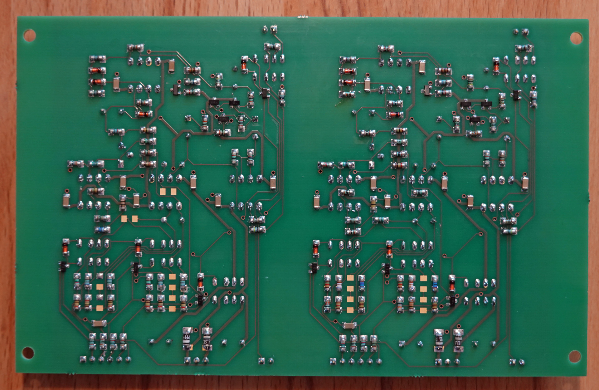 |
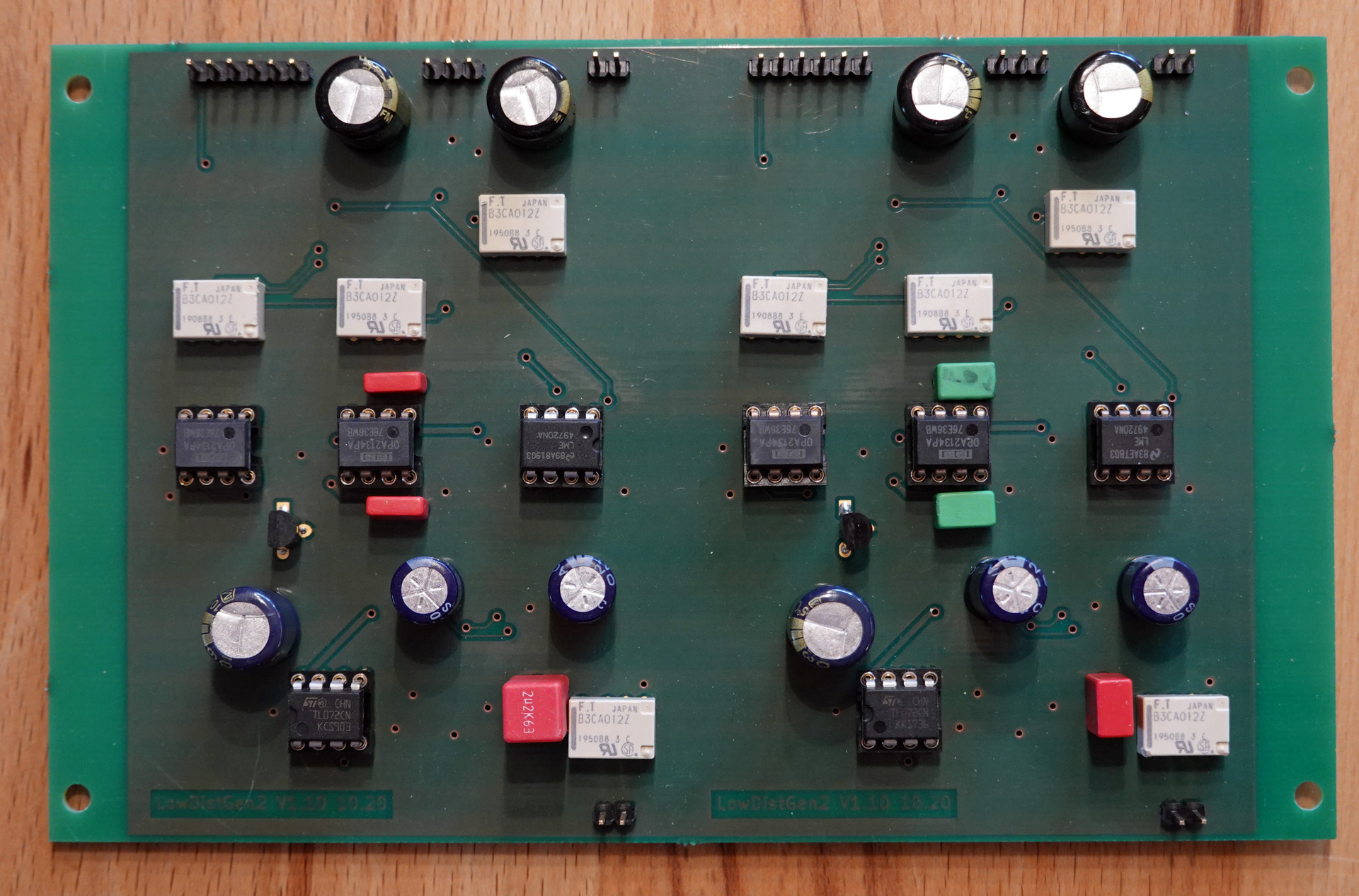
Fig. 2 sine wave generators with 3 frequencies each are on a circuit board. With this, you can already carry out many measurements.
| PCB Gerberfiles | .ZIP | LowDistGen2-V202.zip |
Examples for the frequency calculation. The values for the resistors must of course be adapted to the real capacitance values of C11/C13.With 3 generators and the specified frequencies, one can perform almost all usual distortion measurements. For the measurement of intermodulation distortions, 2 frequencies each must be mixed in the correct ratio via a passive voltage divider.
| Frequenz | C11/C13 | RG | C16 | ||
| 200 | 4,70E-08 | 16931 | R7+R8 / R22+R23 | 16931 | 2u2 |
| 500 | 4,70E-08 | 6773 | R9+R10 / R24+R25 | 6773 | |
| 1000 | 4,70E-08 | 3386 | R16+R17 / R31+R32 | 6773 | |
| 2000 | 4,70E-09 | 16931 | R7+R8 / R22+R23 | 16931 | 470n |
| 5000 | 4,70E-09 | 6773 | R9+R10 / R24+R25 | 6773 | |
| 17000 | 4,70E-09 | 1992 | R16+R17 / R31+R32 | 2822 | |
| 7000 | 2,20E-09 | 10335 | R7+R8 / R22+R23 | 10335 | 470n |
| 10000 | 2,20E-09 | 7234 | R9+R10 / R24+R25 | 7234 | |
| 18000 | 2,20E-09 | 4019 | R16+R17 / R31+R32 | 9043 |