")
")
THD measurement with sound card (<0.00002%)
Today, the PC with the sound card already provides us with basic measuring equipment and software to analyse the harmonics of a signal. Unfortunately, the result is usually not very good, a THD of better than -100dB is rarely achieved. But this is by far not good enough for real high end. I would like to show you a way to improve such systems with little effort. The result is a setup that can achieve a THD of up to -136dB, i.e. 0.000015%.
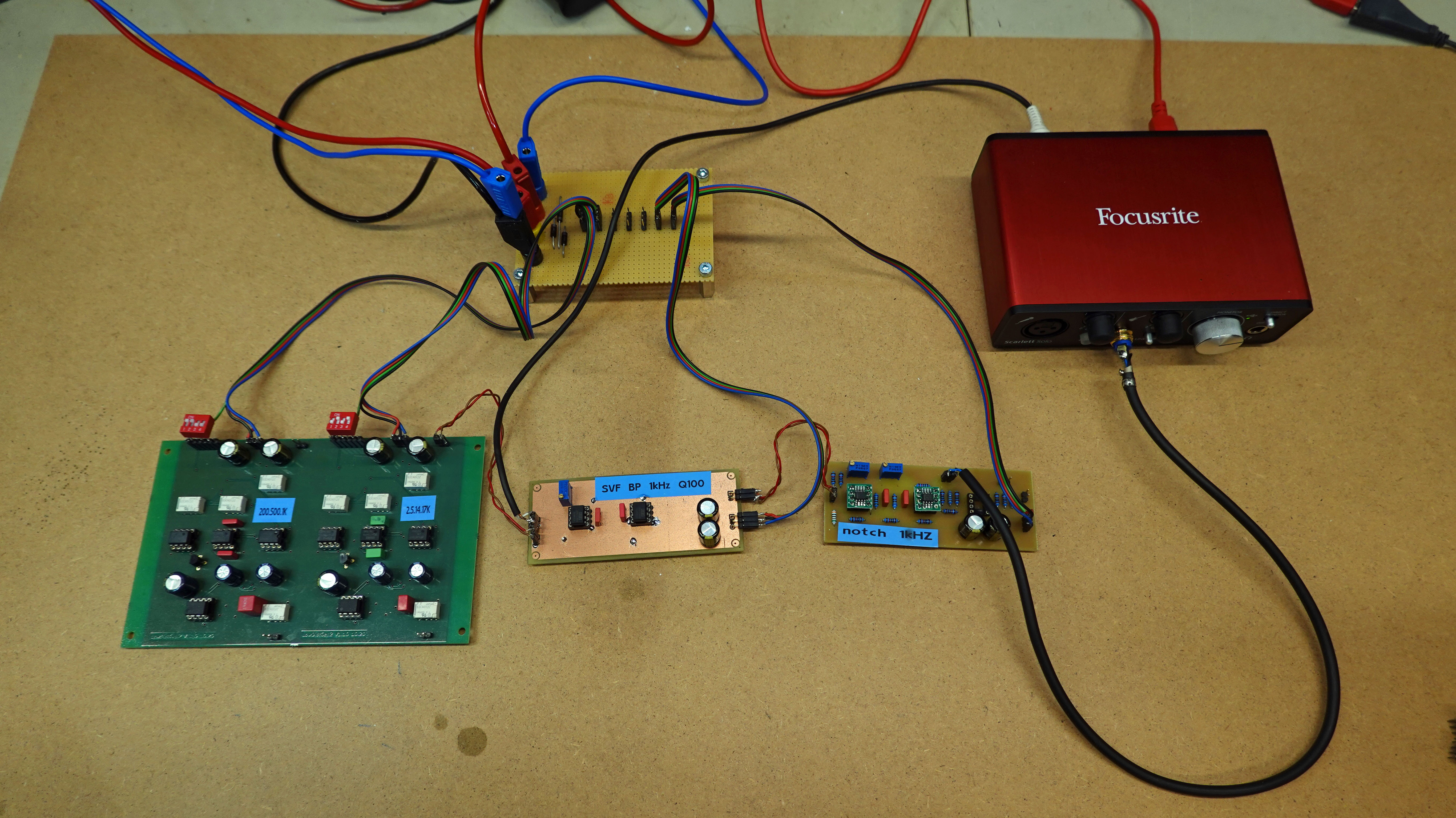
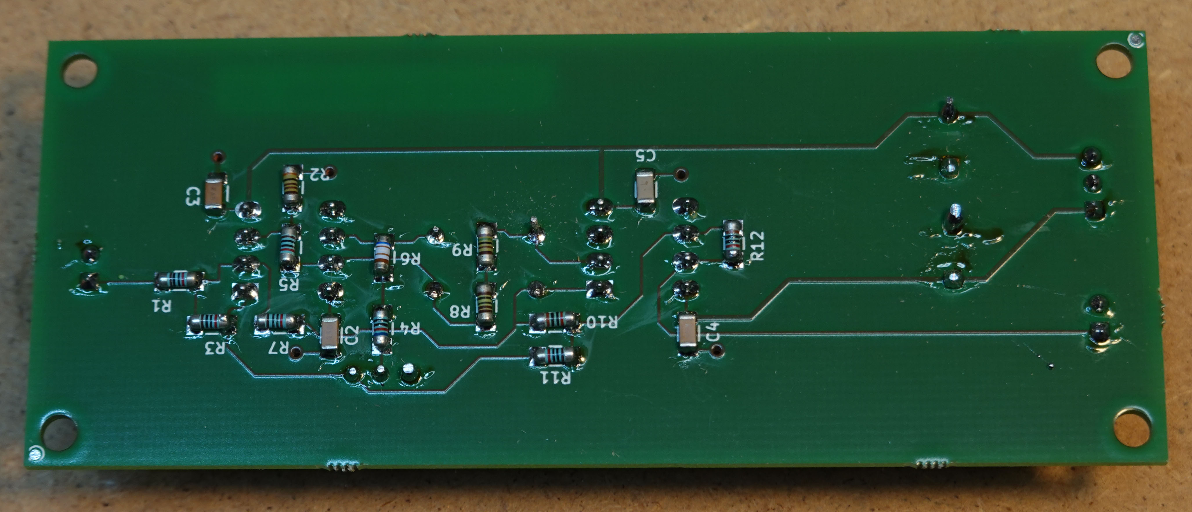
Fig. Example of a measurement setup for the reference measurements. Here, the LowDistGen only provides the reference signal for the -80dB channel. The filters are on self-made circuit boards.
Let's start at the beginning and make a reference measurement, setting the output of the sound card to 1Vrms and looping it through a (built-in) attenuator to the input of the sound card. The amplitude is set as high as possible, but there should not yet be any additional distortion due to overdriving. In my example, I use an external USB sound card from Focusrite and ARTA as analysis software.
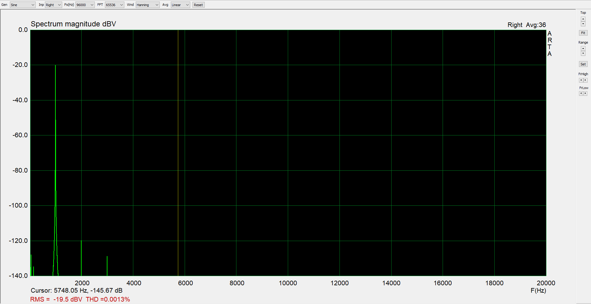
Fig. Reference measurement of the sound card: output directly to input
At 1kHz you see the fundamental attenuated from 0dB to -20dB with the input attenuator of the sound card. K2 is relative to this at approx. -100dB and K3 at approx. -108dB. THD is thus approx. 0.00125%. We are (hopefully) still missing at least one power of ten in quality for the measurement of high-quality high-end components.
As a first step of improvement, one can insert a bandstop for the fundamental wave in front of the receiver. This reduces the amount of distortion from the receiver. The fundamental wave does not have to be completely suppressed. An attenuation of 20dB, better 40dB will already have a significant effect. Of course, it must be ensured that the harmonics pass through the blocking filter as undistorted as possible.
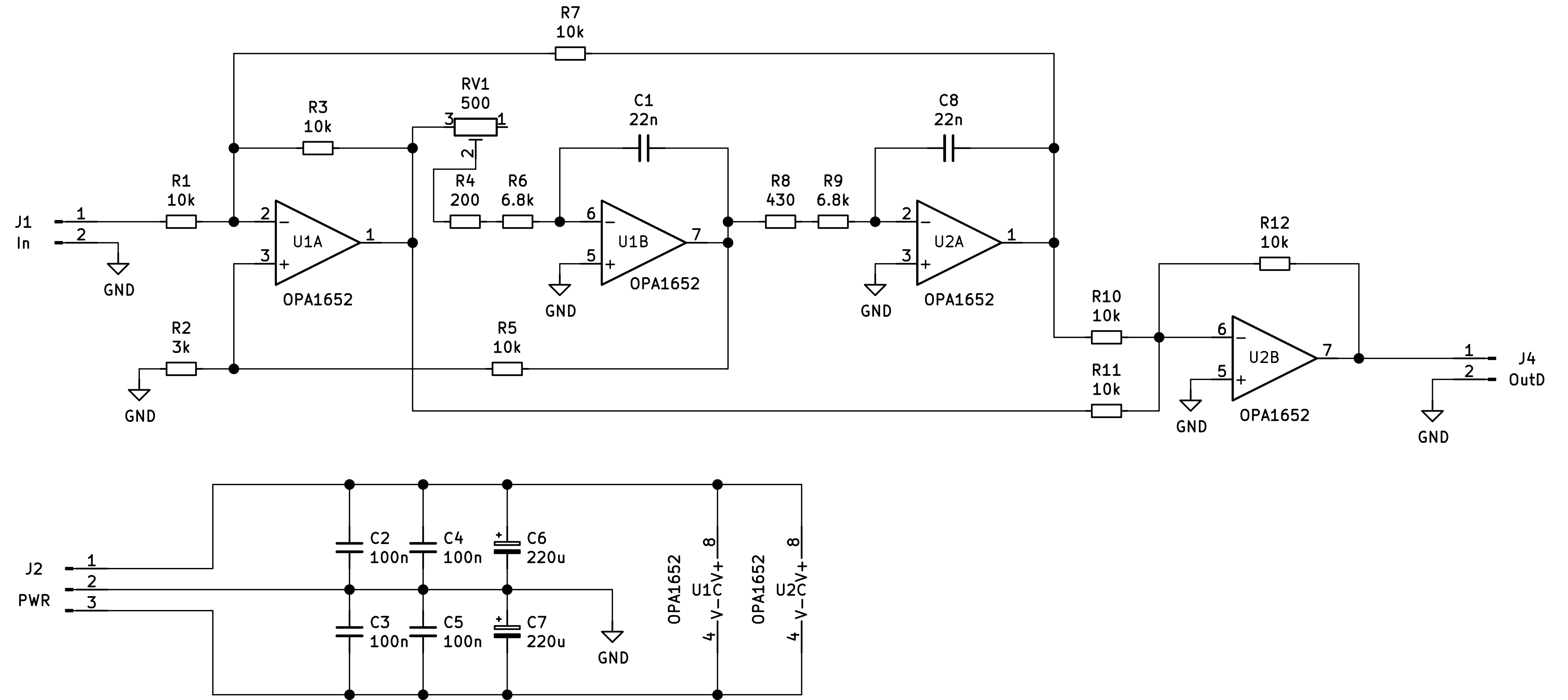
Fig. Circuit diagram basic wave attenuation filter (dimensioning 1kHz)
 |
 |
 |
I use an SVF for the basic wave blocking filter. These are particularly suitable for filters that require adjustment because they can be easily adapted to the requirements by varying individual component values. The quality of the filter can be adjusted with R2, the frequency with a single 10-turn trimmer RV1. For this, however, it is necessary to measure C1 and C2 and to adjust the resistors R8+R9 and R6+R4+RV1 to the capacitance values. Since the output frequency of the sound card is very stable and we are working in a very limited temperature range, this can be done with long-term stability. The dimensioning shown here leads to approx. 40dB fundamental wave attenuation with an attenuation of the first harmonic of less than 0.5dB with my tolerances.
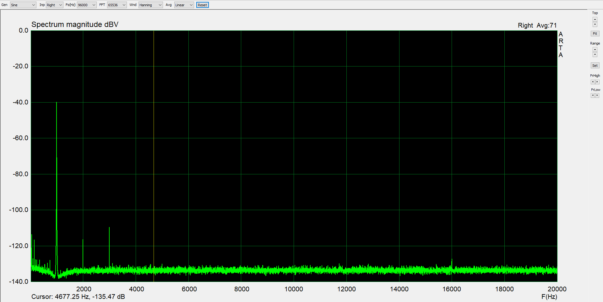
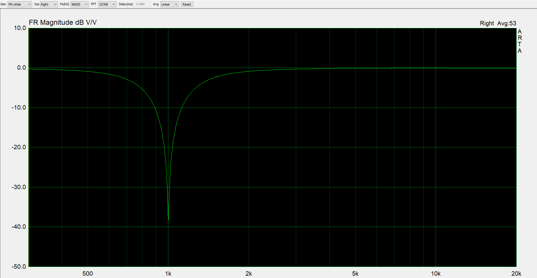
Fig. Reference measurement of the sound card with fundamental wave attenuation filter in front of the receiver
The result is encouraging. At 1kHz you can see the 40dB attenuated fundamental, K2 relative to 0dB at -115dB and K3 at -108dB. THD is thus approx. 0.00045%. Better, but still far from the target.
Especially K3 seems to be an effect of the generator. So here is our next starting point. A bandpass filter connected directly behind the signal output of the sound card, which allows the fundamental wave to pass but attenuates the harmonics, is the next step of the opimisation. This way, the harmonic distortions of the generator should be clearly attenuated. Of course, the inherent distortions of the filter are decisive.
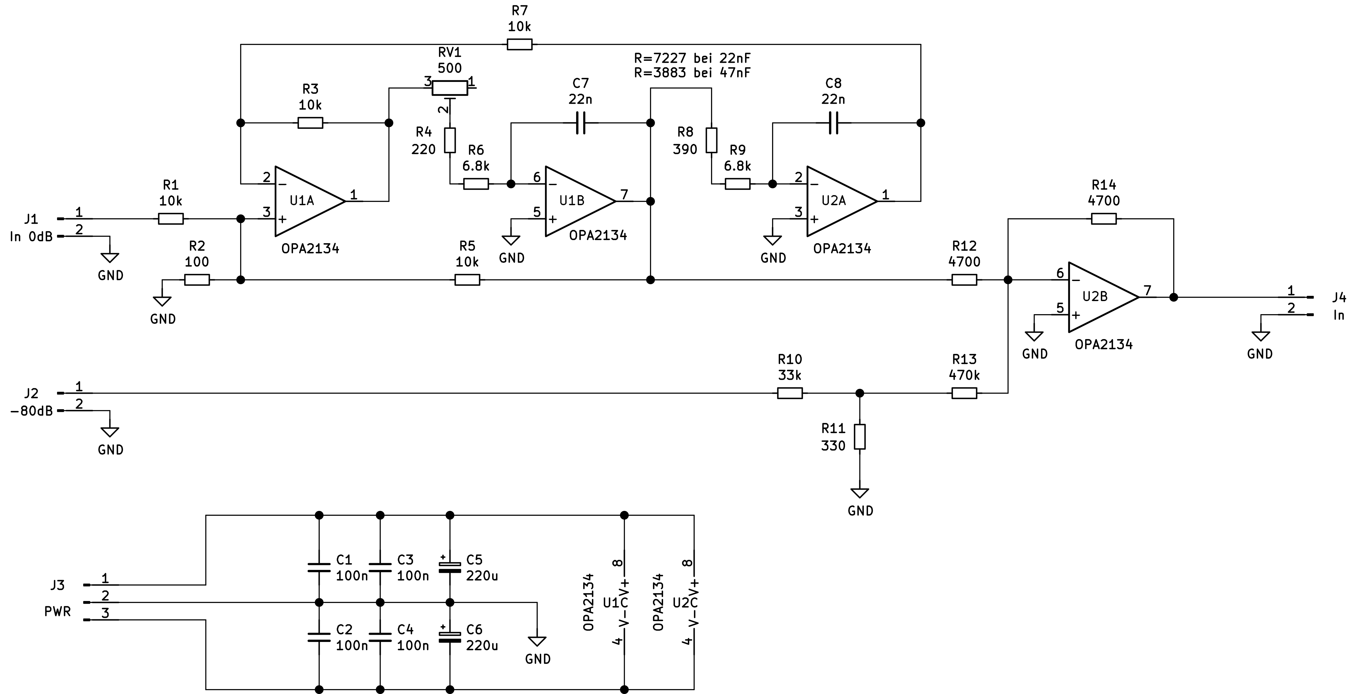
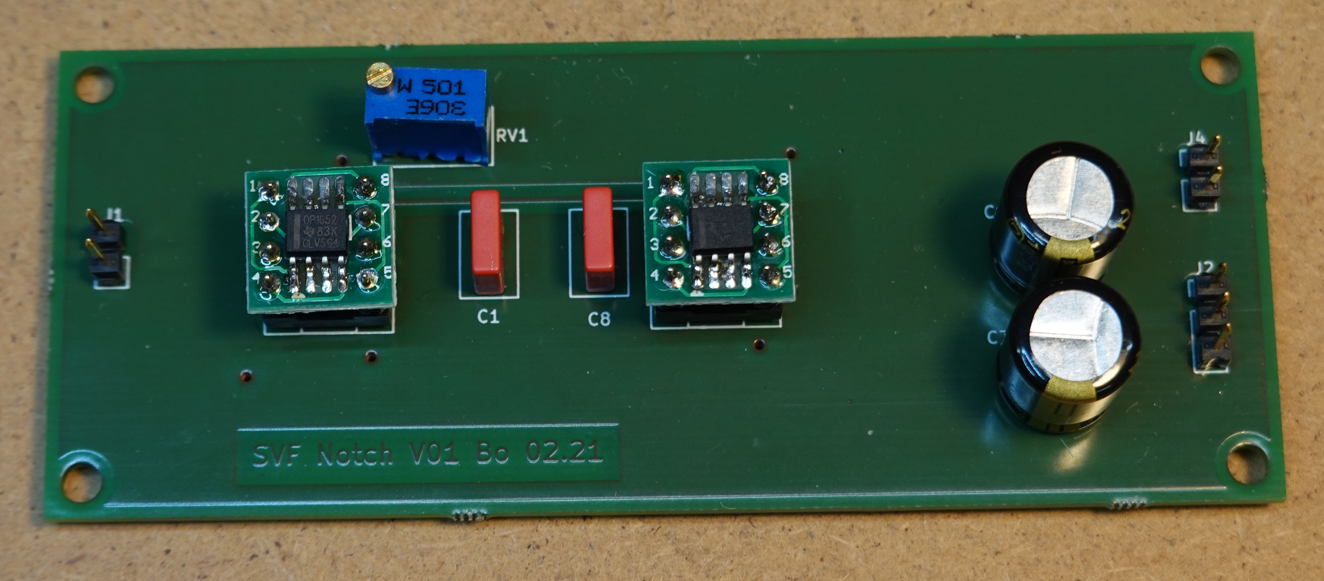
Fig. Circuit diagram of the band-pass filter for harmonic attenuation of the generator (dimensioning for 1kHz)
This filter is also based on an SVF. The quality is set to 100 via R2. C7 and C8 must be measured again and the corresponding frequency-determining resistors RV1+R4+R6 or R8+R8 must be adjusted individually. With R1, the amplification of the fundamental can then be corrected to 0dB in case of deviations. The harmonic attenuation of the first harmonic is >40dB. For this purpose, a -80dB reference signal can be fed in again via J2, which greatly improves the reliability of the evaluation.
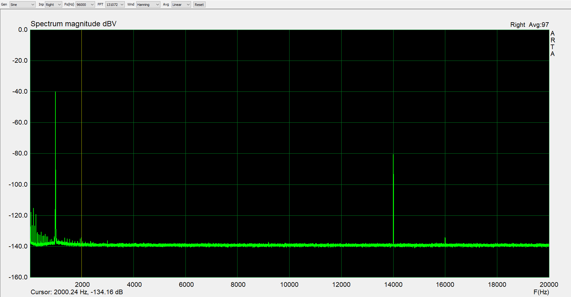
Fig. Reference measurement Sound card with bandpass behind the generator and fundamental wave attenuation filter in front of the receiver
At 1kHz you see the fundamental suppressed by 40dB, at 14kHz the -80db reference tone. K2 is at -136dB and K3 at -138dB relative to the fundamental, the noise floor is at -138dB. The THD is less than 0.00003%. You can do something with that. These values are on the level of professional measuring instruments.
Of course, only at one frequency for the time being. But to realise the whole thing now for 50/100/200/500/1k/2k/5k/10k Hz is very manageable, both in terms of effort and cost.